Laser-drilled microvias connect selected adjacent layers within the buildup structure.
HDI PCB Manufacturing and Microvia Design
GlobalWin reviews HDI PCB manufacturing requirements for fine-pitch BGAs and compact electronics. Coordinate microvias, sequential buildup, impedance and stackup design before releasing fabrication data.
HDI requirements depend on component pitch, routing density, stackup, material, via structure and volume. Final specifications are confirmed during engineering review.
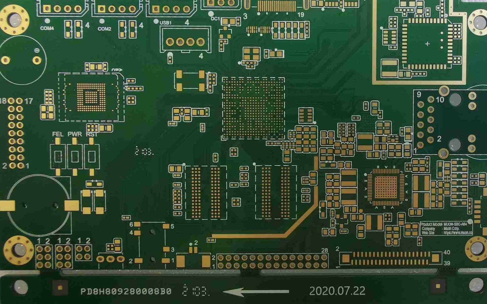
What is an HDI PCB?
An HDI PCB (High-Density Interconnect PCB) uses laser-drilled microvias, fine lines, small pads and sequential buildup layers to route more connections in less board area than a conventional through-hole PCB. It is normally selected for fine-pitch BGAs, compact products and dense high-speed designs.
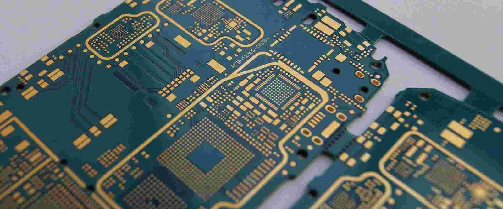
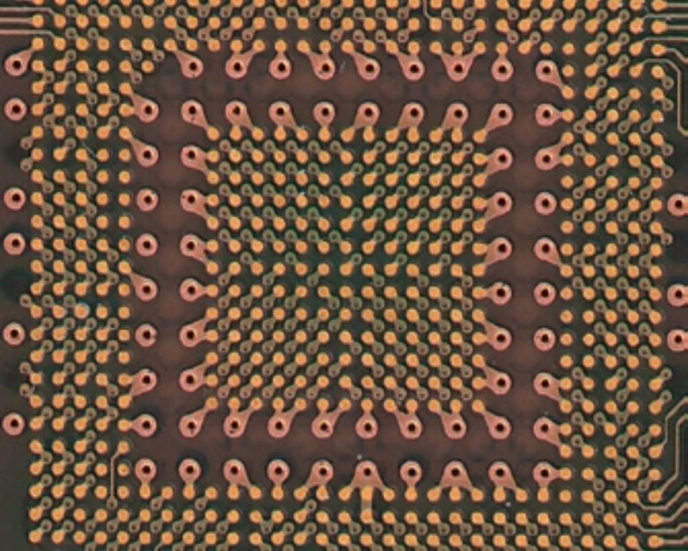
More routing density without simply adding more layers
HDI changes how a PCB uses space. Instead of depending only on full-depth mechanical vias, the design can use laser-drilled microvias and buildup layers to create shorter interconnect paths and more efficient component fanout.
- Support for fine-pitch BGA and area-array components
- More routing flexibility inside compact board outlines
- Shorter via transitions for selected high-speed paths
- Better integration of dense functional blocks
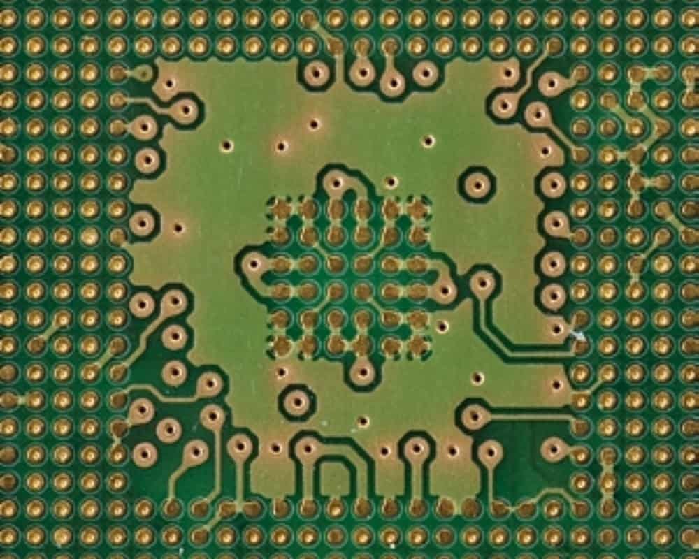
Additional dielectric and copper layers are added in controlled buildup cycles.
Stackup, impedance, via strategy and component escape should be reviewed together.
HDI PCB vs. conventional PCB
The right choice depends on component pitch, board size, routing density, electrical performance and production requirements. HDI is not automatically the best option for every design.
| Design factor | Conventional multilayer PCB | HDI PCB |
|---|---|---|
| Main interconnection | Often mechanical plated through-holes | Microvias and buildup, with other vias as required |
| Routing geometry | Agreed for the copper and fabrication process | Finer routing may be evaluated with the approved process |
| BGA escape | Depends on pitch, pad geometry and routing space | Microvia or via-in-pad fanout may enable denser escape |
| Layer count | Selected from routing, power and reference requirements | May decrease, remain unchanged or increase by design |
| Signal transitions | Includes full-depth via and stub considerations | Selected short microvia transitions can be useful |
| Fabrication | Core, lamination, drilling, plating and patterning | May require repeated buildup, drilling and via filling |
| Cost | Construction-specific quotation | Includes the extra process and qualification scope |
On smaller screens, scroll this table horizontally to compare all columns.
These values are design references, not guaranteed production capabilities. Confirm line width, spacing, drill size, annular ring, registration and material limits with your PCB manufacturer before releasing the design.
When should you choose HDI PCB technology?
HDI becomes useful when conventional routing can no longer deliver sufficient component escape, board size, signal integrity or layer efficiency.
Fine-pitch BGA fanout
Choose HDI when BGA pitch and pad arrangement leave insufficient room for conventional dog-bone fanout.
Compact product outline
HDI helps integrate more functions into small products such as portable devices, sensors and embedded modules.
Dense high-speed routing
A carefully planned via structure reduces unnecessary transitions along high-speed paths.
Layer-count optimization
HDI can deliver the required density with a more efficient architecture instead of adding conventional layers.
HDI PCB Stackup Planning for Density and Reliability
An HDI stackup should be reviewed before routing starts. Dielectric thickness, copper weight, reference planes, microvia depth, impedance targets and lamination sequence all shape the manufacturable result.
Illustrative stackup only. Production stackups are confirmed against the approved material system and impedance requirements.
What should be reviewed before layout?
A manufacturable HDI design is not defined by one microvia dimension. The full buildup architecture must support drilling, lamination, copper fill, registration, electrical test and final assembly.
Define core and buildup layers
Establish core layer count, buildup layers, overall thickness and layer-to-layer connection strategy.
Set impedance targets early
Single-ended and differential targets must connect to trace width, copper thickness and dielectric geometry.
Choose staggered or stacked microvias
The via arrangement affects routing flexibility, copper filling requirements and process complexity.
Check thermal and mechanical constraints
Board thickness, copper distribution and assembly conditions matter as much as routing density.
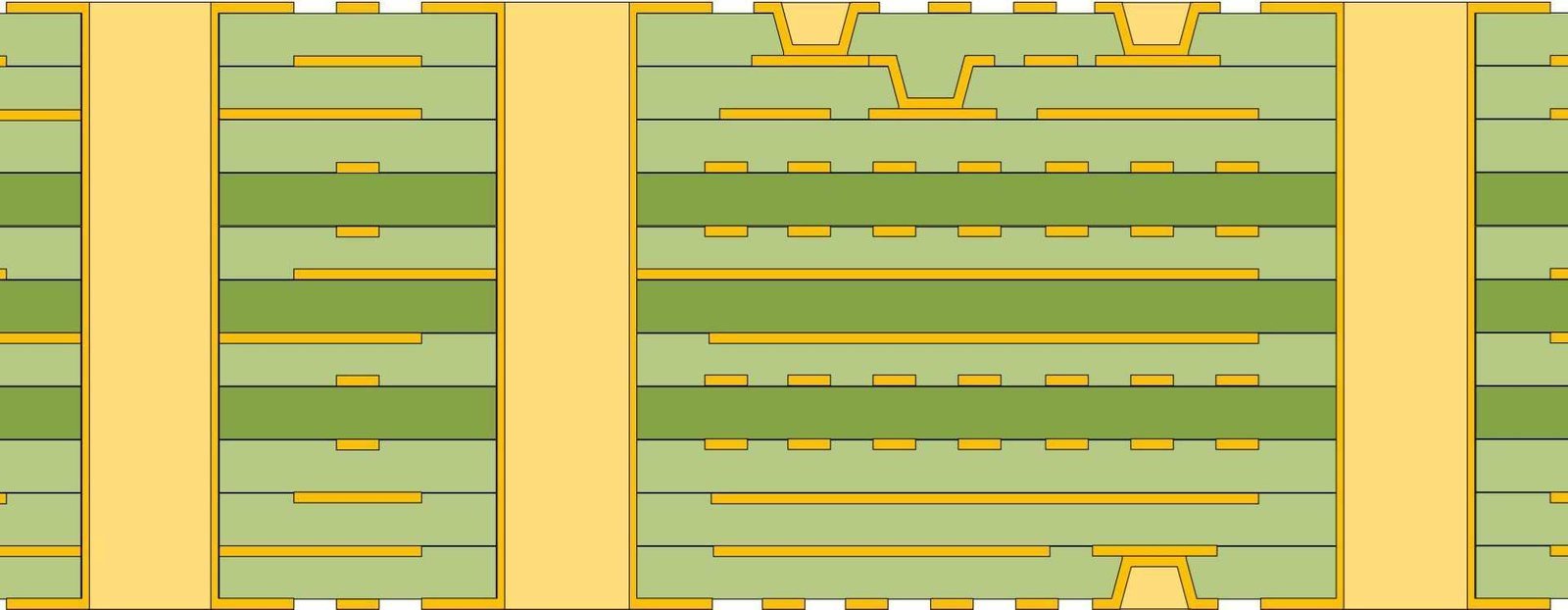
Microvia and via structures used in HDI PCB design
Different via technologies solve different routing and escape problems. Choosing the simplest structure that meets the requirement helps control risk and manufacturing complexity.
Microvia
A small laser-drilled via that typically connects adjacent layers inside a buildup structure.
Blind via
Connects an outer layer to one or more inner layers without passing through the full board thickness.
Buried via
Connects internal layers and stays inaccessible from the outer surface after lamination.
Via-in-pad
Places a via inside a component pad to improve escape routing. Copper filling and planarization may be required.
From HDI design review to production-ready boards
HDI manufacturing requires coordination between design data, stackup, laser drilling, lamination, via filling, surface finish and inspection.
- 01
Engineering Review
Check files, smallest BGA pitch, layer pairs, impedance and reliability requirements.
- 02
Approve the Stackup
Confirm materials, core and buildup structure, copper and dielectric thicknesses.
- 03
Fabricate the Inner Structure
Form and inspect the core circuitry and any required buried interconnects.
- 04
Laminate a Buildup Layer
Add the approved dielectric and copper in the planned lamination sequence.
- 05
Drill, Metallize and Repeat
Form microvias, complete filling and circuit patterning as specified, then repeat for additional buildup layers.
- 06
Finish, Inspect and Test
Complete surface finish, electrical test and agreed microvia or reliability evidence.
What to Ask an HDI PCB Manufacturer
A reliable HDI program depends on process control as well as electrical test. Documentation should make critical dimensions, materials, via structures and inspection results traceable.
Microsection verification
Review buildup thickness, copper connection and via geometry from cross-section evidence.
Dimensional and registration control
Check finished dimensions, pad alignment, layer registration and critical clearances.
Electrical and impedance testing
Apply continuity, isolation, flying probe or fixture testing as the project requires.
Production documentation
Keep the approved stackup, fabrication notes, inspection records and revision history aligned.
HDI PCB manufacturing FAQ
Clear answers to common questions about HDI structures, microvias, stackups, design files and manufacturing planning.
What is the difference between an HDI PCB and a standard PCB?
Which HDI stackup should I choose?
Does HDI always reduce the total layer count?
When is via-in-pad required on an HDI PCB?
Can HDI PCBs use FR-4 material?
What information is needed for an HDI PCB quotation?
Let’s review your next build.
Share your fabrication files, quantity and assembly requirements.