Specify coverlay openings
Include pad access, opening dimensions, overlap and registration requirements. Coordinate coverlay with soldering, bonding and the installed bend position.
GlobalWin reviews flexible PCB manufacturing requirements for polyimide FPCs and flex circuits. Plan the material, bend conditions, coverlay, stiffeners and fabrication data together before requesting a quotation.
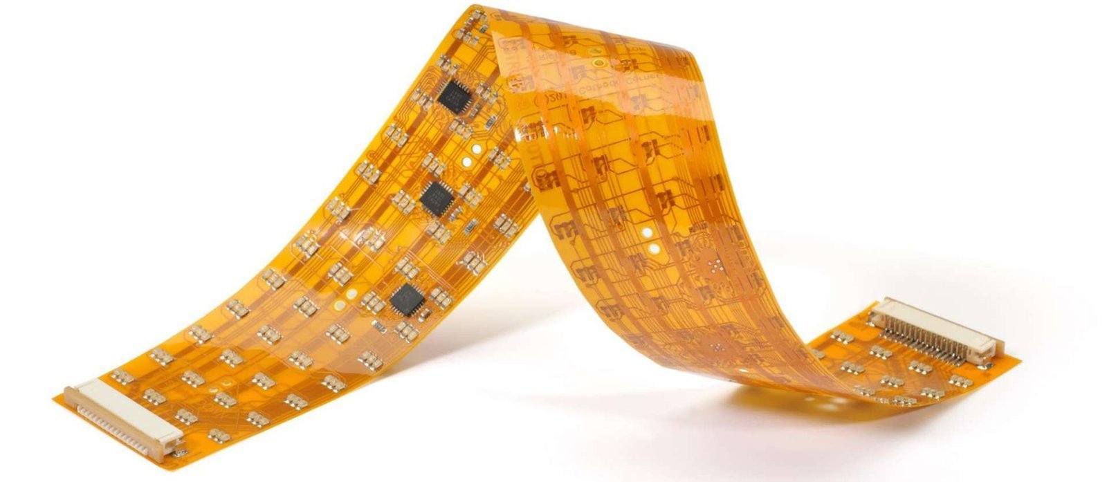
A flexible PCB is a printed circuit board manufactured on a bendable dielectric substrate, commonly polyimide. It is used to route electrical signals through folded, curved or space-constrained assemblies.
A flexible printed circuit board combines a dielectric film, conductors and protection layers. Adhesives and stiffeners depend on the chosen construction.
Polyimide (PI), Polyester (PET), or LCP film providing flexibility and insulation.
Rolled Annealed (RA) or Electrodeposited (ED) copper carrying electrical signals.
Adhesive-based or adhesiveless copper-clad construction; an adhesiveless laminate does not have a separate copper-to-film adhesive layer.
Polyimide film with adhesive protecting conductors from environmental exposure.
Compare flexible PCB materials by the exact laminate grade, assembly process, moisture exposure and bend duty. Film properties alone do not establish the operating limits of the finished flex circuit.
A common starting point for polyimide flex PCB designs. Match the laminate, copper, coverlay and bonding system to the assembly and mechanical requirements.
An option for selected cost-sensitive flexible circuits. Confirm conductor technology and assembly temperature compatibility rather than substituting PET for a solderable PI construction.
An alternative to evaluate when moisture or high-frequency performance drives the specification. Manufacturing route and availability require confirmation.
Copper foil selection affects mechanical performance. Rolled annealed (RA) copper is often considered for repeated bending, but a copper label alone does not establish a flex-cycle rating.
RA copper is commonly evaluated for demanding bend applications. Confirm the foil grade, thickness, grain orientation, plating in the bend zone and representative cycle testing.
Electrodeposited copper covers multiple foil grades. Suitability depends on ductility, construction and the specified bend duty; do not assume all ED foils have identical mechanical behavior.
Minimum bend radius depends on the finished flex thickness, number of copper layers, copper type, bend direction, bend frequency and the required service life.
The bend ratio relates the inside bend radius to the finished thickness of the flexible section. The acceptable ratio must be agreed for the actual stackup and motion profile.
r = k × tr: bend radius · t: flex thickness · k: agreed ratioExample only: a 0.10 mm flex section and an assumed ratio of 10 give a 1.0 mm radius. This arithmetic example is not a recommended minimum. Keep vias, pads and rigid supports out of the active bend unless specifically qualified.
| Bend condition | Design information | Confirmation basis |
|---|---|---|
| Static installation bend | Installed shape, radius, angle and expected re-forming | Approved bend drawing and material construction |
| Repeated dynamic flex | Cycle target, motion speed, radius and environment | Representative mechanical and electrical testing |
| Multilayer flex | Copper-layer count, bonding and neutral-axis location | Construction-specific engineering review |
| Rigid-flex transition | Rigid edge, coverlay termination and keepout zones | Coordinated mechanical and fabrication drawings |
Supplier recommendations can differ by construction. Compare rigid-flex bend guidance with the approved project requirements; do not treat a generic ratio as an IPC acceptance rule.
On smaller screens, scroll this table horizontally to compare all columns.
Proper trace routing, pad geometry and copper distribution are essential for flex circuit reliability.
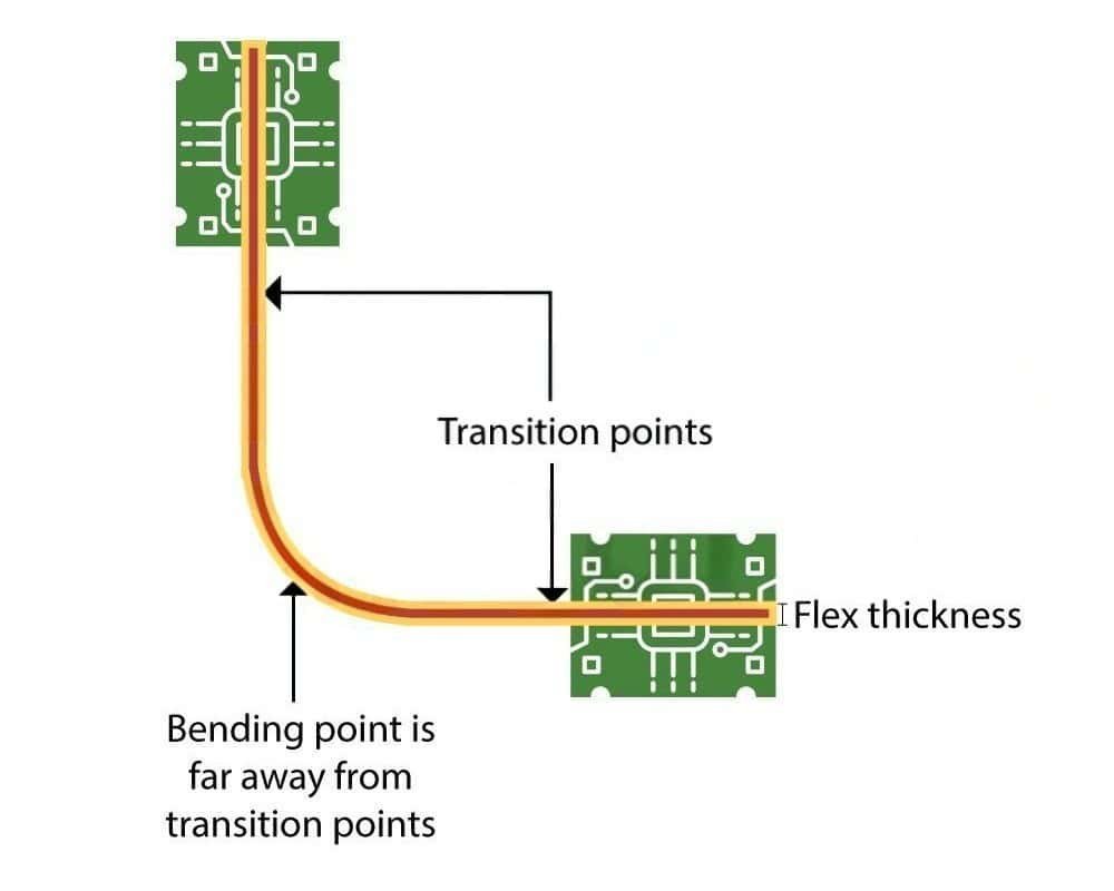
Coverlay protects conductors while leaving access to pads. Stiffeners support areas such as connectors or component zones, rather than increasing the electrical layer count.
Include pad access, opening dimensions, overlap and registration requirements. Coordinate coverlay with soldering, bonding and the installed bend position.
State material, finished thickness, adhesive, location and which side of the FPC is supported. Keep the stiffener edge and associated strain outside the active bend where practical.
For a flex PCB prototype, use the same approved construction and bend conditions planned for validation. A prototype photograph alone is not evidence of production reliability.
When selecting a flexible PCB manufacturer, compare the complete construction and inspection scope. Use the fabrication package to agree achievable dimensions and tolerances; the checklist is not an approved factory capability table.
| Requirement | Provide with your enquiry | What must be agreed |
|---|---|---|
| Layer count and thickness | Flex layer count and finished construction | Rigidized zones, bonding system and tolerances |
| Trace width and spacing | Critical geometry and copper thickness | Etching, plating and yield requirements |
| Drilled holes and vias | Finished dimensions, pads and layer connections | Registration, annular ring and bend keepouts |
| Coverlay | Openings, access pads and overlap | Process tolerance and minimum bridges |
| Stiffeners | Material, thickness, location and adhesive | Assembly support and connector fit |
| Impedance | Target, tolerance, reference layers and controlled nets | Approved stackup, geometry and test coupons |
| Prototype and production | Quantity, revision and qualification scope | Material availability, test plan and quoted schedule |
Technical parameters are project-dependent. Actual capability should be confirmed during DFM review.
On smaller screens, scroll this table horizontally to compare all columns.
A static flex circuit is formed during installation and remains mostly stationary. The allowed radius and number of installation bends depend on its actual construction.
Typical applications include folded interconnects between rigid board sections, space-saving circuit routing, and three-dimensional assemblies.
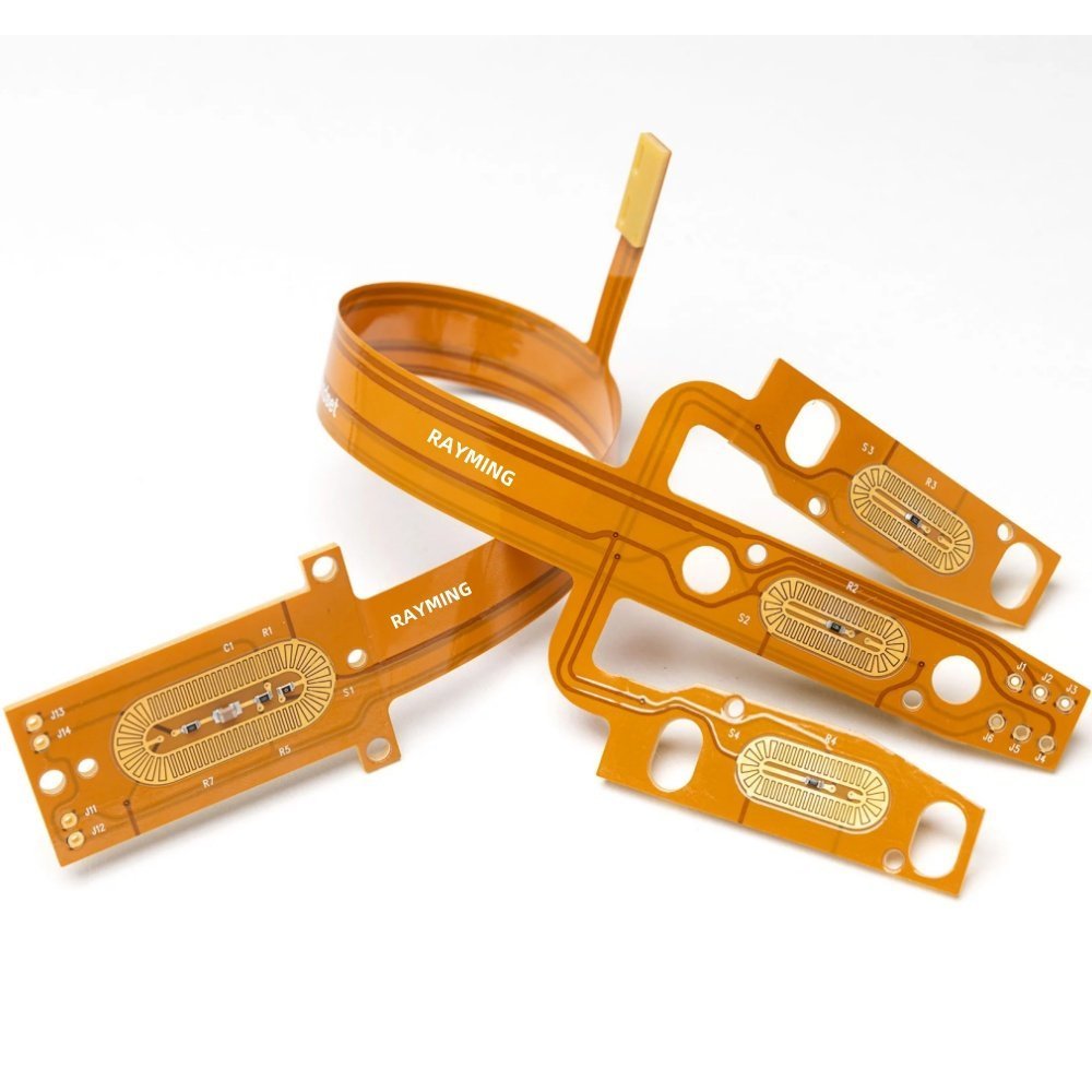
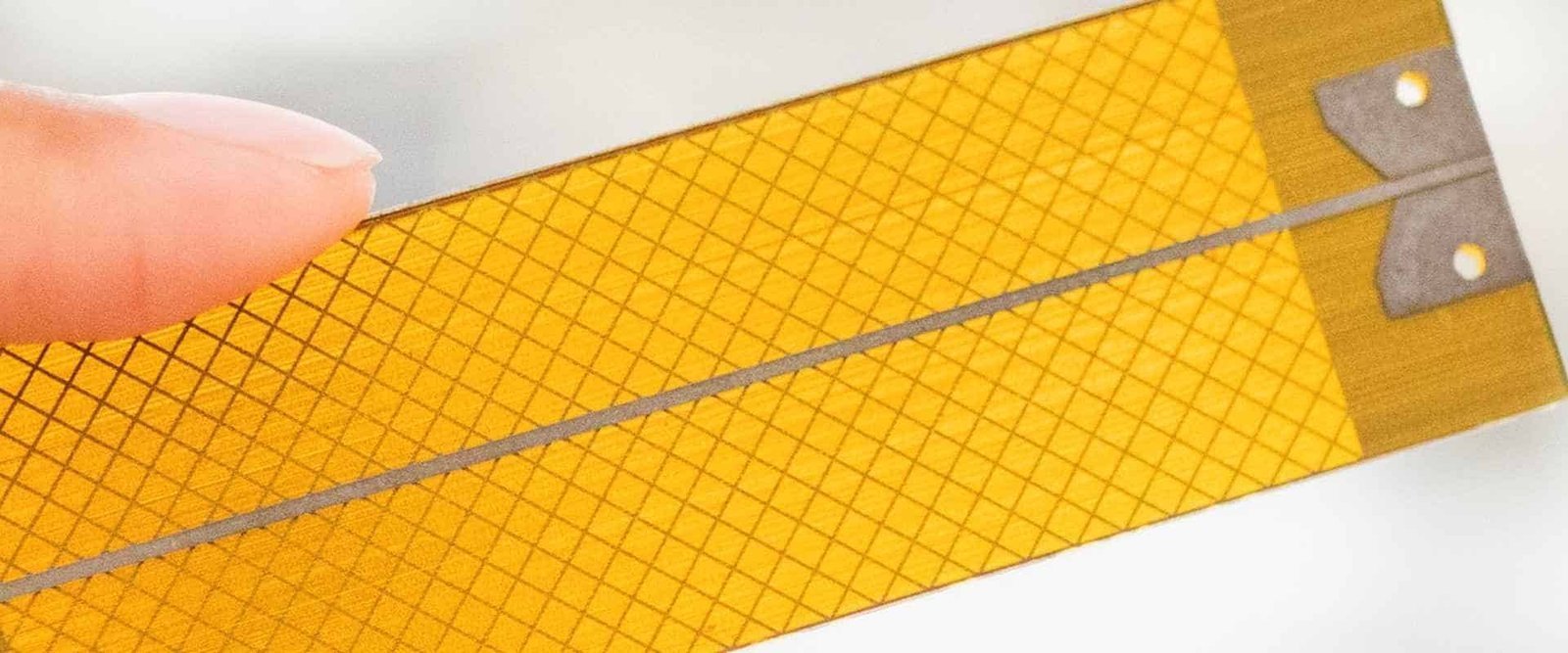
A dynamic flex circuit bends repeatedly during operation. Review foil grade, copper thickness, bend radius, trace geometry and cycle testing together; there is no universal cycle-life rating.
Typical applications include hinged displays, articulating robotic arms, moving scanner assemblies and folding consumer electronics.
A flexible PCB is a printed circuit board manufactured on a bendable dielectric substrate, commonly polyimide. It is used to route electrical signals through folded, curved or space-constrained assemblies.
Static flex is formed into a position during assembly and remains mostly stationary. Dynamic flex is designed to bend repeatedly during product operation and requires additional attention to copper type, thickness, bend radius and trace geometry.
Polyimide is a common starting material for flexible PCB designs because it supports thin constructions, elevated assembly temperatures and repeated mechanical movement. PET and LCP may be considered when cost, temperature, moisture or high-frequency requirements call for a different material system.
Minimum bend radius depends on the finished flex thickness, number of copper layers, copper type, bend direction, bend frequency and the required service life. Dynamic applications generally need a larger bend radius than static formed flex.
Yes. Components can be assembled on designated rigidized areas or supported component zones. Stiffeners, pad geometry, thermal conditions and the assembly process should be reviewed before production.
A quotation normally requires fabrication data, layer count, material preference, copper weight, finished thickness, surface finish, stiffener details, flex-zone drawings, quantity and any impedance, testing or assembly requirements.
A flexible PCB uses a flexible base and may include stiffeners or supported component zones. A rigid-flex PCB integrates rigid laminate sections and flexible interconnect regions in one board; a stiffened flex circuit is not automatically a rigid-flex construction.
The construction should follow the installation geometry, component mounting needs and expected movement.
A bendable circuit used for compact interconnects. Specify static or dynamic use, bend area, thickness and copper construction.
Rigid board sections and flexible interconnects in an integrated construction. Review transitions, stackup and component keepouts.
Send a mechanical drawing, stackup, bend radius, flex cycles and assembly temperature requirements. Final feasibility is project-specific.
Share your fabrication files, quantity and assembly requirements.